Flammability test equipment directly measures a material's reaction to fire. It quantifies critical metrics: ignition time, flame spread rate, burning duration, and self-extinguishing ability. During a test, the machine exposes a properly prepared sample to a controlled flame, heat source, or electrical current. This standardized environment creates repeatable, objective results for accurate fire-safety classification. You will learn the general workflow, from sample preparation and controlled ignition to observation and key measurements. It also covers specific device types, including the Automatic Flammability Tester, Horizontal Flammability Test Equipment, and SPI Flammability Tester, and explains their unique measurement approaches.
Key Takeaways
-
Flammability test equipment measures how materials react to fire, including ignition time and flame spread.
-
Vertical tests are harsher than horizontal tests because flames spread upward faster.
-
Flash point and autoignition temperature help classify fire risks for safe storage and handling.
-
Flammability testing ensures products meet safety standards and guides material selection.
-
Choosing the right tester depends on your material and industry standards.
How Flammability Test Equipment Works
Flammability test equipment follows a defined sequence. You prepare a sample, expose it to a controlled ignition source, and watch how it burns. Each step matters for accurate results.
Preparing and Mounting Samples
Sample preparation starts with cutting the material to a standard size. ASTM D635, which covers horizontal burning of plastics, requires a specimen 125 mm long, 13 mm wide, and the thickness to be rated. You then condition the sample under controlled temperature and humidity. This step removes moisture variation that could skew results.
Mounting depends on the test type. For the ASTM E84 Steiner tunnel test, you mount a conditioned sample 24 inches wide and 24 feet long inverted on the ceiling under a removable lid. For textile tests at a 45-degree angle, CPSC guidelines direct you to clamp each specimen between two metal plates with the burn side facing up. Raised-surface fabrics need brushing against the lay of the fibers. You then condition mounted specimens in an oven for 30 ±2 minutes at 105° ±3 °C (221° ±5 °F), cool them over desiccant for at least 15 minutes, and test at a 45° angle with a one-second flame application.
Proper mounting ensures the flame contacts the sample the same way every time. This consistency makes results repeatable across different labs.
Ignition and Observation
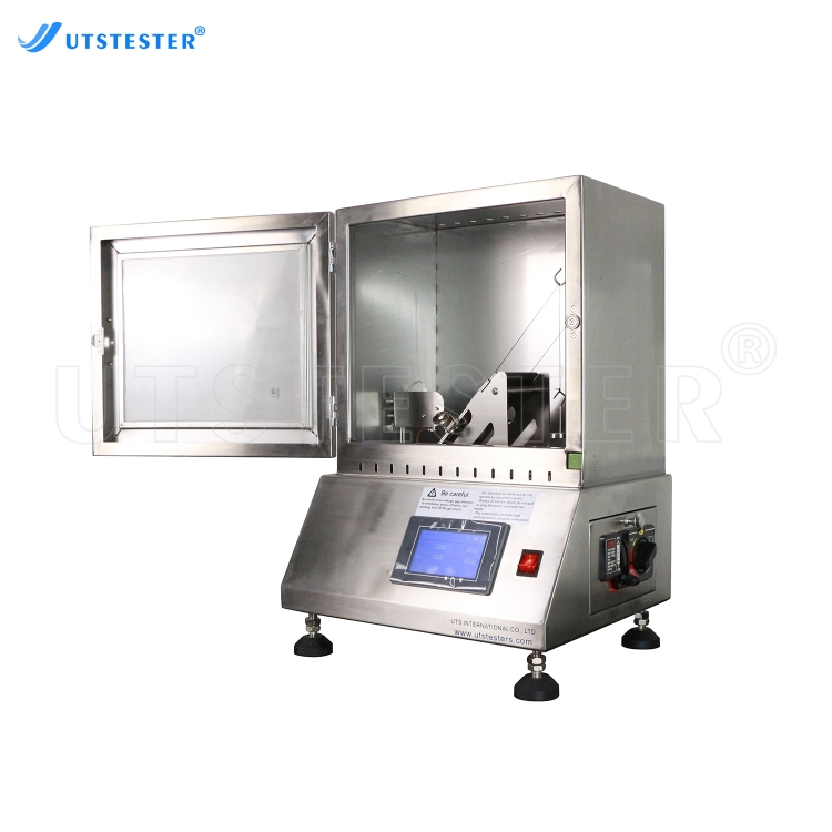
Once mounted, the sample meets a controlled flame. Many setups use a bunsen or tirrill burner with a gas flame at a fixed distance from the sample edge. An Automatic Flammability Tester can regulate flame application time and positioning with high precision. For UL 94 vertical burn tests, standard V materials receive two 10-second flame applications, while thin materials (VTM) receive two 3-second applications.
During ignition, you observe several parameters. ISO 5658 identifies time of ignition as the primary parameter during this phase, along with time of extinction and flame front travel. After the flame source withdraws, you record the flame time after removal of the burn source. You also note whether drippings ignite the cotton below and measure the flame time of drippings. A material that can self-extinguish when no longer in contact with flames earns a better rating.
These parameters are critical in determining whether the material meets safety standards such as IEC 60695-11-5, which applies specifically to flammability testing of electrical components.
The entire process runs under standardized conditions. Every variable — flame intensity, exposure duration, sample position — stays fixed. This control lets you compare results across materials, batches, and laboratories. The minimum ignition energy of a material also influences how quickly it catches fire under a given spark or heat source. Reliable test equipment and procedures give you data you can trust for safety decisions.
Types of Flammability Testing Equipment
Different materials demand different testers. You will find specialized flammability test equipment for plastics, textiles, cables, and construction products. Each type applies flame or heat in a specific orientation and measures distinct burn behavior.
Vertical and Horizontal Flame Testers
Vertical flame testers hold the sample upright and apply flame from below. This orientation creates the harshest conditions because flames travel upward along the material. You use vertical tests for electrical equipment, cables, textiles, and construction panels. The UL 94 standard for plastics defines three vertical ratings: V-0, V-1, and V-2. These ratings differ in how long the material burns after you remove the flame.
|
Criterion (vertical test)
|
V-0
|
V-1
|
V-2
|
|
Afterflame time for each specimen (t1 or t2)
|
≤ 10 s
|
≤ 30 s
|
≤ 30 s
|
|
Total afterflame time for five specimens
|
≤ 50 s
|
≤ 250 s
|
≤ 250 s
|
|
Afterflame plus afterglow after second application (t2 + t3)
|
≤ 30 s
|
≤ 60 s
|
≤ 60 s
|
|
Flaming or glowing combustion up to the holding clamp
|
No
|
No
|
No
|
|
Flaming drips that ignite cotton 300 mm below
|
No
|
No
|
Yes (allowed)
|
A V-0 rating demands the strictest performance. The material must self-extinguish quickly and must not produce flaming drips. You also track the flame time of drippings to confirm whether particles ignite the cotton below.
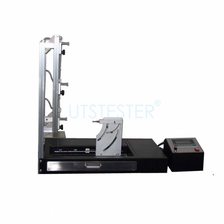
Horizontal Flammability Test Equipment positions the sample flat. Flames spread more slowly in this orientation. You use horizontal tests for automotive interior materials, where the burn rate must be less than 100 mm/min. The SPI Flammability Tester follows this horizontal configuration and serves the plastics industry for quality control.
The flame application time for horizontal flammability tests on automotive interior materials is approximately 15 seconds.
You measure the acceptable burn length after the flame withdraws. Different industries choose different orientations. Electronics manufacturers rely on vertical tests for circuit boards. Automotive suppliers use horizontal tests for dashboards and seat fabrics. Medical device makers test both ways depending on the product housing.
Limiting Oxygen Index Testers
A limiting oxygen index tester measures the minimum oxygen level that sustains combustion. You place a sample in a controlled atmosphere and adjust the oxygen-nitrogen mix. The limiting oxygen concentration tells you how easily a material burns in normal air. A higher limiting oxygen concentration means the material needs more oxygen to burn.
This tester gives you a single number for material comparison. You can rank plastics, textiles, and foams by their fire resistance. Materials with a high limiting oxygen concentration self-extinguish in ambient air. The limiting oxygen concentration also predicts behavior in confined spaces. Aircraft and motor vehicles both require materials with elevated oxygen index values. The same data helps you select materials for motor vehicles and airplanes where fire risk is critical.
These flammability tests produce data that supports material selection across industries. Each tester type answers a specific safety question.
Flash Point and Autoignition Temperature Testing
Measuring Flash Point
Flash point testing identifies the lowest temperature at which vapors ignite when exposed to a flame. This data helps you classify flammable and combustible liquids and gases for safe storage and handling. Two main methods exist: open cup and closed cup testing.
Open cup tests, such as the Cleveland Open Cup (ASTM D92-18), leave the liquid surface uncovered. Vapors escape freely, so ignition requires a higher temperature. Closed cup tests, like the Pensky-Martens (ASTM D93-20), seal the sample with a lid. Vapors accumulate inside, producing lower flash point values. For the same product, closed cup results measure 5–10 °C lower than open cup results. This makes closed cup data more conservative for safety assessments.
The closed cup method mimics real conditions in sealed drums or tanks. It provides a closer approximation of the temperature at which vapor pressure reaches the lower flammable limit. For safety data sheets, you typically report closed cup flash point values. The flash point of a material directly determines its hazard classification.
For viscous liquids, the Pensky-Martens tester uses Procedure B. It heats the sample at 1 to 1.5 °C per minute while a paddle stirs continuously at 0–300 RPM. This prevents surface films and ensures uniform heating. An electronic detection system registers ignition automatically.
Knowing the lower flammability limit and upper flammability limit of a substance defines its flammable mixture range. These flammability limits describe the concentration window where a flammable mixture can form. Defining the flammability limits of each substance requires careful, consistent testing. Understanding these flammability limits helps you evaluate explosion severity in process safety. Lower flash point values indicate greater fire risk during handling.
Determining Autoignition Temperature
Autoignition temperature testing determines the point where a material ignites without an external spark. This differs from flash point testing, which requires an ignition source. ASTM E659-15 covers the test method for liquid chemicals. You place a sample in a heated flask and observe the autoignition temperature at which spontaneous combustion occurs.
Natural gas has a minimum autoignition temperature of 600 °C. Common polymers autoignite at lower values. Polyethylene autoignites at 226 °C, and polypropylene has an autoignition temperature of 201 °C. The autoignition temperature of a substance helps you define safe operating limits in your facility.
The autoignition temperature connects to minimum ignition energy. A material with a lower autoignition temperature needs less energy to ignite spontaneously. This influences explosion severity in industrial processes where hot surfaces exist. The limiting oxygen concentration also determines whether a flammable or explosive mixture can form.
Combining flash point and autoignition temperature data gives you a complete fire risk picture. These values support safer product design and standards compliance. Flash point and autoignition temperature testing is a cornerstone of industrial fire safety evaluation.
The Significance of Flammability Testing
Safety and Compliance
Flammability testing gives you the data you need to judge real fire risk. A material that self-extinguishes quickly and resists flame spread poses less danger in a building, vehicle, or device. You use these results to decide where a product can safely go and how it must be handled. Without this information, you would guess at safety, and guessing is not acceptable when lives depend on the answer.
Regulators also rely on this data. Under the EU Construction Products Regulation, manufacturers generally must issue a declaration of performance and apply the CE marking before placing most construction products on the market. CE marking eligibility depends on meeting the applicable harmonized standard's essential characteristics, including fire safety. EN 13501-1 assesses reaction-to-fire performance, and its results classify products into fire performance classes that strongly influence where those products can be used. These classes align with the categories in the Delegated Regulation on reaction-to-fire classification, except that EN 13501-1 does not include the additional "electric cables" class found in the regulation. The significance of flammability testing therefore reaches beyond the lab bench and into legal market access.
Product Design and Risk Assessment
Engineers use flammability characteristics to guide material selection early in design. If a plastic housing must meet a strict vertical burn rating, you choose a formulation that self-extinguishes fast and avoids flaming drips. If a dashboard material must limit burn rate, you pick one that passes the horizontal test. These choices shape the final product long before production begins.
Risk assessment depends on the same numbers. Flash point and autoignition temperature data tell you how a substance behaves during storage and handling. A low flash point signals greater fire risk, so you add controls. A low autoignition temperature means hot surfaces could start a fire without a spark. Manufacturers like UTS International supply flammability test equipment to support safer products and standards compliance. With proper test equipment, you turn raw measurements into informed decisions that protect users and meet global requirements.
This equipment measures fire reaction. You prepare and ignite samples, then observe burn behavior. Flash point and autoignition temperature testing produces ignition data. A flash point identifies lowest vapor ignition temperature. This flash point value classifies liquid hazards. You use flash point results for safe storage. Flash point testing uses open or closed cup methods. Closed cup flash point provides conservative safety data. A lower flash point means greater risk. Flash point indicates handling fire risk. Flash point measurement supports hazard classification. Flash point and autoignition temperature define a safety profile. Autoignition temperature shows ignition without spark and influences safe limits and explosion risk. Reliable flammability test equipment from UTS International supports safety.
FAQ
What does flammability test equipment actually measure?
It measures how a material reacts to fire. You record ignition time, flame spread rate, burning duration, and self-extinguishing behavior. The equipment also tracks the flame time of drippings and whether particles ignite cotton below the sample. These measurements produce objective data for fire-safety classification.
Why do vertical and horizontal flame tests give different results?
Orientation changes how flames travel. A vertical tester holds the sample upright, so flames spread upward and create harsher conditions. Horizontal Flammability Test Equipment lays the sample flat, where flames spread more slowly. You choose the orientation that matches your product's real-world position.
How does a limiting oxygen index tester differ from a burn test?
A limiting oxygen index tester finds the minimum oxygen level that sustains combustion. You adjust the oxygen-nitrogen mix and observe when the material stops burning. This gives you the limiting oxygen concentration, a single number for ranking fire resistance across plastics, textiles, and foams.
What is the difference between flash point and autoignition temperature?
Flash point testing finds the lowest temperature where vapors ignite with a flame. Autoignition temperature testing finds where a material ignites without any spark. A low flash point signals greater handling risk. A low autoignition temperature means hot surfaces alone could start a fire.
How do flammability limits affect industrial safety?
Flammability limits define the concentration window where a flammable mixture can form. You need both the lower flammability limit and upper flammability limit to assess risk. These values, along with minimum ignition energy, help you evaluate explosion severity and set safe operating controls in your facility.
Which tester suits my material?
An Automatic Flammability Tester handles precise flame timing for UL 94 vertical tests. The SPI Flammability Tester serves horizontal plastics testing. Your choice depends on the material and industry. Electronics, automotive, and medical device makers each follow different standards and orientations.


 +86 152 6060 5085
 English
 русский
 español
 português
 العربية
 Polski



 hello@utstesters.com
 hello@utstesters.com
 +86 152 6060 5085
 +8615260605085